Next: Code Construction and Entropy Up: Image Analysis Previous: Two-Dimensional Gabor Filters
![]()
![]()
![]()
Next: Code Construction and Entropy Up: Image Analysis Previous: Two-Dimensional Gabor Filters

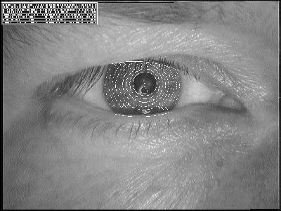
Figure 3: Demarcated zones of analysis and illustration of a computed iris code.
Zones of analysis are established on the iris in a doubly dimensionless projected polar coordinate system. Its purpose is to maintain reference to the same regions of iris tissue regardless both of pupillary constriction and overall iris image size, and hence regardless of distance to the eye and video zoom factor. This pseudo polar coordinate system is not necessarily concentric, since for most eyes the pupil is not central in the iris. (Typically the pupil is both nasal to, and inferior to, the center of the iris [1], and it is not unusual for its displacement to be as great as 15%.) The stretching of the elastic trabecular meshwork of the iris from constriction of the pupil is intrinsically modelled by the doubly dimensionless projected coordinate system as the stretching of a homogeneous rubber sheet, having the topology of an annulus anchored along its outer perimeter, with tension controlled by an off-centered interior ring of variable radius.
The homogeneous rubber sheet model assigns to each point in the iris, regardless
of size and pupillary dilation, a pair of dimensionless real coordinates
(r,Ø) where r lies on the unit interval [0,1] and ![]() is the usual angular quantity that is cyclic over [0,2
is the usual angular quantity that is cyclic over [0,2![]() ]. The remapping of the iris image I(x,y) from raw coordinates (x,y) to the doubly dimensionless non-concentric polar coordinate system (r,
]. The remapping of the iris image I(x,y) from raw coordinates (x,y) to the doubly dimensionless non-concentric polar coordinate system (r,![]() ) can be represented as
) can be represented as
where x(r,![]() ) and y(r,
) and y(r,![]() ) are defined as linear combinations of both the set of pupillary boundary
points (xp(Ø), yp(Ø)) around the circle that was found to maximize operator (4), and the
set of limbus boundary points along the outer perimeter of the iris (xs)(
) are defined as linear combinations of both the set of pupillary boundary
points (xp(Ø), yp(Ø)) around the circle that was found to maximize operator (4), and the
set of limbus boundary points along the outer perimeter of the iris (xs)(![]() ),ys(
),ys(![]() ) bordering the sclera, that was found to maximize operator (3):
) bordering the sclera, that was found to maximize operator (3):
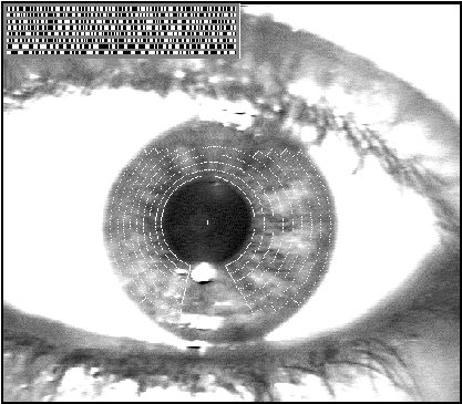
Demarcations of the zones of analysis specified in this projected doubly dimensionless coordinate system, for two sample close-up iris images, are illustrated in Figures 3 and 4. These zones of analysis are assigned in the same format for all eyes and are based on a fixed partitioning of the dimensionless polar coordinate system, but of course for any given eye their affine radial scaling depends on the actual pupillary diameter (and possible offset) relative to the limbus boundary as determined by operators (3) and (4). The zones of analysis always exclude a region at the top of the iris where partial occlusion by the upper eyelid is common, and a 45° notch at the bottom where there is a corneal specular reflection from the filtered light source that illuminates the eye from below. (Illumination at an angle is desirable to deflect its specular reflection from eye-glasses, which persons are not asked to remove. The much greater curvature of the cornea compared with that of spectacle lenses, however, prevents elimination of the illuminator's first Purkinje reflection from the moist lower front surface of the cornea or of contact lenses; this necessitates the exclusion notch in the zones of analysis near the 6-o'clock position.)
Rotation invariance to correct for head tilt and cyclovergence of the eye within its orbit is achieved in a subsequent stage of analysis of the iris code itself. The overall recognition scheme is thus invariant under the Poincaré group of transformations of the iris image: planar translation, rotation (due to cyclovergence and tilt of the head), and dilation (due both to imaging distance and video zoom factor). Through the doubly dimensionless coordinate system, the constructed iris code is also invariant under the non-affine elastic distortion (or projected conic transformation) that arises from variable pupil constriction.

Figure 4: Demarcated zones of analysis and illustration of a computed iris code.
![]()
![]()
![]()
Next: Code Construction and Entropy Up: Image Analysis Previous: Two-Dimensional Gabor Filters